
Designed in Siemens NX6
 This is tutorial for one of many ways to use WAVE linking in NX6. Idea was to make plane wing that can be changed with simple change of values in Tools>Expressions. I tried to make this from one part, but it is too complicated to be really useful, so I made it with assembly and wave linking to keep it simple and functional.
In video below you can see how wing geometry is changed with change of values in expressions:
Next set of images show how to make this kind of design. Keep in mind that WAVE linking have great potential in design, and that this is just one of many ways to use it. It is one of most impressive technologies I saw so far in NX.
Air profile is done by importing points of air profile (I used NACA 6412 profile) and then scale it do get full size root profile.
 Same have to be done for tip profile. (tip profile can be same or different from root profile, for this tutorial I used same NACA 6412 profile but I imported them with different attack angle)

 Make first sketch, on XY plane, it is simple line with start in 0,0,0 with angle toward X axis of 'wing angle' and length of 'half span'.
 Make a associative plane from line from previous sketch and Z axes. Make a new sketch on that plane. In this sketch make again onl one line from 0,0,0 this time with 'dihedral angle' toward first line, or if you expect negative "anhedral" angle make it from Z axes but as '=90-dihedral angle' (this is because in NX sketch you can not make negative angle dimension). If you want to have length of span as projection on XY plane then make vertical line from end of line from previous sketch to end of line in this sketch. To make it more simple for this example I just used 'half span' length as length of this line.
 Two more sketches, one at XZ plane where you will place root profile with only one line (this one line thing become boring?) make angle from Z axes with '=90+root attack angle' value, so it can go both + and - way.
 Make new plane for last sketch, have to be associative, parallel to XZ plane and to go through end point of line we draw in sketch with dihedral angle. Make a sketch on that plane. This time two lines, one vertical and one at '=90+tip attack angle' value from first line.
 Part should look like picture below at this stage.
 Now this part become assembly. Assembly> component> add component, add both profiles (root and tip profile parts).
 Constrain tip profile: profile plane XZ parallel to assembly XZ plane, WCS origin of tip profile touch/align with end of line from sketch with 'dihedral angle' dimension, X axes of tip profile with line from sketch that have 'tip attack angle' dimension.

 Constrain root profile: profile plane XZ touch/align with assembly plane XZ, profile Y axes touch/align with assembly Y axes, and profile X axes touch align with line from sketch that have 'root attack angle' dimension.

 Now Insert> Associative copy> WAVE geometry linker, and add both profiles to our assembly part as associative WAVE geometry.
 Use new WAVE geometry to make ruled surface.


In video below you can see how wing geometry is changed with change of values in expressions:
Next set of images show how to make this kind of design. Keep in mind that WAVE linking have great potential in design, and that this is just one of many ways to use it. It is one of most impressive technologies I saw so far in NX.
Air profile is done by importing points of air profile (I used NACA 6412 profile) and then scale it do get full size root profile.


Save profiles in separate files.
Now make new file which will be used to parameterize our wing.
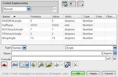
First make expressions in tools>expressions.
- half span [length-mm =3000]
- wing angle [angle-degrees =75]
- dihedral angle [angle-degrees =5]
- root attack angle [angle-degrees =7]
- tip attack angle [angle-degrees =2]


Now you can play with expressions to see how wing update as you change expressions values.
For more interesting model i added one more level of WAVE linking. I made new part and added wing we got in last assembly as linked geometry and then I made a model of wing flaps area to see how it will update with changes of parameters in previous part. You can see it yourself in next few images.


how did you import naca 6412 file to nx6?
ReplyDeleteThis comment has been removed by a blog administrator.
ReplyDeletehi sudeep, i deleted your double post :)
ReplyDeleteand when you download NACA profile it is set of coordinates for points, so i used insert>curve>spline>through points>point from file... then you select point file and then you get spline through set of NACA points.
Hello
ReplyDeleteCan you explain why you use wave linker instead of working directly with the part or assembly?
And why do you say that is better to work with the assembly instead of a part?
(I guess is because you want to use wave linker?
regards
Maybe i am wrong but i do not know how you can keep control of spline position in one part? this model have two splines (NACA profiles), and angle and position of these two splines control shape of wing. i used linking to obtain control of position and angle oe these two splines.
Deleteif you have idea how to mamke this in one part i will like to hear and i will be happy to make new post with your solution for this problem.